Cheap STM32 dev board fiddlings
The Prelude #
The STM32 has garnered some attention lately as a possible successor/upgrade for the limited AVR microcontrollers that most Arduinos use. I’m not sure why it has captured the spotlight away from other interesting options, such as the Freescale part used in the Teensy. Perhaps that’s only my perception. There is certainly room enough for multiple nifty alternatives.
As is common, the place to go for cheap and cheerful if slightly dodgy electronical goodness is Banggood. They don’t disappoint with the STM32, as we have this fine option for only $5 shipped.
The board is fairly well appointed. It is based on the F103C8T6 variant, with a pinout that exposes nearly all of the chip’s IO. If you read the datasheet, you’ll find the chip is packed with interesting features, including two 12bit ADCs, 3 hardware UARTS, multiple hardware SPI/I2C interfaces, and screams along at “up to” 72mhz.
Of course, you can’t use all these features at once due to limited pins, in this case, a “mere” 48. The variant on the Banggood board has 64k of flash, which can also be a bit limiting. For the price though, it is hard to beat. Digikey charges over $6 for a bare chip! (at one-off quantities)
The Setup #
But on to the reason for this post. The board ships with no documentation, and given the friendly looking USB (mini, not micro, curses!) port, you could be forgiven for assuming you’ll have a straightforward programming experience, like that with the Arduino. Out of the box, that is most certainly not the case.
While there are apparently ways to put an Arduino-ish firmware on the board, which may unlock that level of ease-of-use, and even use of the Arduino IDE (ugh), I didn’t look into that. I want to use STM’s tools along with OpenOCD to write to the bare silicon in glorious, unlimited C.
The first thing you’ll need is a programmer board that supports OpenOCD. Rather than rattle out options, I’ll point you to the “Choosing a Dongle” section of OpenOCD’s documentation. There are oodles of choices, many of which can be had for less than $30. I already had two supported “dongles,” Olimex’s fantastic ARM-USB-TINY-H, and the crazy versatile Bus Pirate. I decided to use the Olimex device for my experimentation today.
One word of warning: not all dongles support debugging. You’ll probably want this at some point, and one of the cheapest options, a clone of the J-Link V8, will give you full debug support. Ebay has quite a few options for about $25. It also supports the Segger software apparently, though using it with that is in a gray area of legality. If you stick to OpenOCD, you can keep your conscience from twitching. OpenOCD is awesome, so why look elsewhere?
I’m going to continue assuming you have my exact hardware. Hopefully you can figure out how to tweak things if you have a different dongle.
After installing OpenOCD (I built the 0.9 release without trouble on my Ubuntu 16.04 machine), I created a config file for the board, which was ridiculously simple.
source [find interface/ftdi/olimex-arm-usb-tiny-h.cfg]
source [find target/stm32f1x.cfg]
You can find configuration scripts for all the supported dongles wherever your OS of choice stuffs shared components. For me, it was /usr/local/share/openocd/. If you intend to use any of the FTDI based boards, take note of the ftdi subdirectory in my config file. There is a script in the root of the interface directory with the same name (olimex-arm-usb-tiny-h.cfg). If you use this file, OpenOCD will explode with a puzzling error, as it uses a deprecated driver for the FTDI chip that this and several other boards are built upon. This driver is disabled by default. I think they should have moved the deprecated configuration files somewhere else to prevent confusion. It would have saved a few minutes of head scratching.
The next thing is a “nice to have.” STM provides a free, cross-platform GUI to help you configure your MCU. This is important because the more advanced chip features are much more involved to set up compared to Arduino style pin input/output directives. Plus, there are interactions between features that are non-obvious. Certain features won’t work while others are enabled, or have specific pins they must use.
The setup isn’t magical, and you can certainly figure it out on your own, but the GUI helps reduce the cognitive load. Additionally, the code-gen automatically moves in all the includes and libraries required to build/link. This is arguably even more important, as setting up the requirements can be a bit complicated.
To build, we need a cross complier. I used the GNU ARM Embedded Toolchain, installed via this PPA. It installed cleanly and without issue.
Lastly, if you’d like to replicate my setup, you’ll want to have cmake installed and working properly. Cmake is a happy thing, and I never want to use gnu make again. Generally, setting up Cmake is as easy as installing the package with your OS’s package manager. Unless you are running Windows, which makes everything more complicated.
My make files are largely based on those provided in this excellent post on the CLion blog. You can check them out in this gist. I used CLion, but most of my experience should apply to other IDEs, or even just an editor. The make files will work from the command-line as is, just remember to pass -DCMAKE_TOOLCHAIN_FILE=stm32f103.cmake when you build so CMake uses the arm toolchain.
The Blinkin' Project #
My project of choice to test things out is the well loved “Blinky” LED thingie that has become the hello world of the hardware world. Replicating this with the above-mentioned toolchain is surprisingly straightforward.
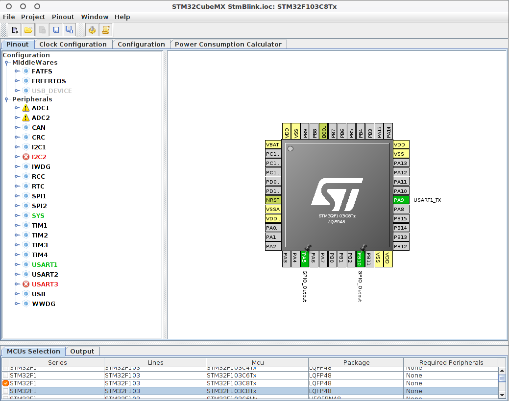
First, in the STM32Cube app, which I’m going to call Cube from now on because it is easier to type, I created a new project. Make sure you carefully find the correct chip in the list. The numbers are many, and it is somewhat confusing. It is possible to change the chip later if you get it wrong, but getting it right to start is more fun. Right? Right.
Next, wire a pin to GPIO Output. This is super easy in STM’s tool. Just click the pin and pick “Output.” In the screenshot below you can see my final configuration, with a few more pins configured. You can use any of the general purpose pins except pin 2. Whatever you do, do not use pin 2! More about that later.
Then, go to Project->Generate Code and select a toolchain. The GCC toolchain isn’t in the list for some reason, but SW4STM32 seems to work reasonably well. On the “Code Generator” tab, make sure “Keep User Code” is checked. When you edit Src/main.c later, you’ll see user code comment blocks throughout. If you place your code in these sections, in new files, or in new sections following the template of the others, you can use Cube to tweak and regenerate at will, without losing anything. Unless you forget and write something outside the marked sections. Not that I did that. Nope. Didn’t need to use CLion’s local history to restore it, either.
Quick aside. I found it instructive to use CLion’s local history to examine the changes that Cube made to the various files. I know all the details are in the documentation. If you want your head to explode with complexity overload, feel free to read the documentation. I kid. It really isn’t that bad. Mostly.
Now, stuff the Cmake files from the gist into the folder created by the code generation step, and you should be able to build. Huzzah! The output of a build confusingly comprises several files. The most important of which is the .hex file that will appear in the build subdirectory. That is what we’re going to flash to the board. Well, once we make it do something slightly more interesting.
Open up Src/main.c, and in the while(1) endless loop, set up the familiar blinky. The syntax isn’t that scary. It is much better than some other MCUs I’ve fiddled with, thanks to some nice abstractions.
  while (1)
  {
  /* USER CODE BEGIN 3 */
      HAL_Delay(1000);
      HAL_GPIO_TogglePin(GPIOA, GPIO_PIN_5);
  /* USER CODE END 3 */
  }
Do a quick build and we’re ready to flash the flashy. Hopefully you’ve gotten OpenOCD up and running. Now is the time for us to make use of that preparation. Start it up, and you should see something like this:
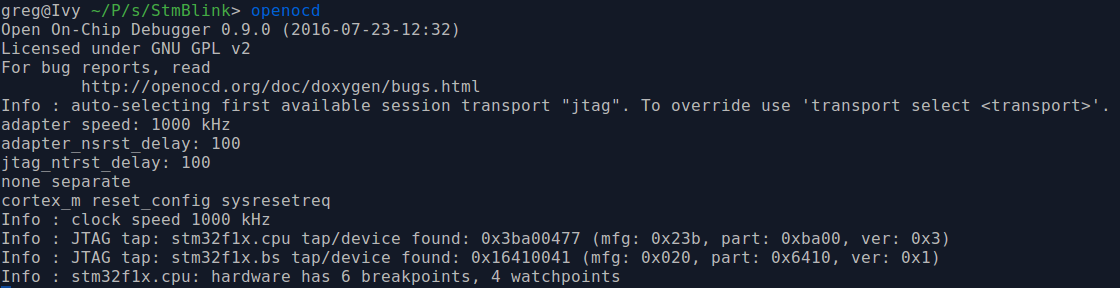
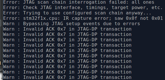
If you see this instead, stick around until the gotchas section for some tips.
Working with OpenOCD is a little odd. It starts up a telnet server (and a GDB compatible widget for “remote” debugging, more on that later) you use to interact with the JTAG daemon.
To flash your file, simply connect on port 4444 like this: telnet localhost 4444 and you can then run program build/r1_blink.hex. It will trundle a moment and hopefully report success. There are a number of much harder ways to flash the chip that you may have found while Googling around. This way has worked fine for me every time. I’m sure there is a reason for the more complicated methods, though.
Now at this point, I think you are meant to reset the board with reset run or reset halt, the latter of which should break at the first line of code and patiently allow you to attach a debugger. For reasons that I don’t yet understand, I had to hard reset the board before my code would execute.
Connect pin 5 to your LED, through a resistor (I used 470 ohms) and to ground. It should be blinking! You can now marvel at using all that MCU power to replicate a 555 based circuit. I won’t judge.
The Gotchas #
If you messed something up, and tried to restart OpenOCD to flash again, you will have stumbled on the first gotcha. I don’t know the cause of this yet, but once I flashed my board the first time, I could not get back into bootloader/JTAG mode without bringing the BOOT 0 pin high. It must remain high or the JTAG connection stops working.
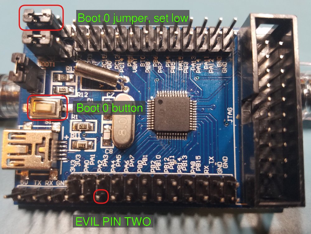
I suspect this is how it is meant to work, and the programmer is supposed to signal debug mode or something, and isn’t doing so correctly. The board has a momentary button that brings BOOT 0 high, and once you do this, you can reconnect via JTAG, but I wasn’t able to get the board in a state to reflash without power-cycling. There is a jumper to keep the pin high, and I found it easiest to set that, reboot, flash and then remove it. I’ve marked these in the (poorly lit) photo below.
This brings me to debugging. It should be possible. I’ve yet to figure it out. I’m unsure if it has something to do with my software/hardware configuration, the phase of the moon, or I’m just doing something wrong. I’ll make a followup post if/when I figure it out.
One other problem I ran into is Evil Pin 2. Evil Pin 2 was my first choice but unfortunately it is “special,” at least on this particular board. If you look at the schematic that OlliW42 helpfully reverse engineered, you can see PB2 is tied to BOOT1. Cube will happily let you make it GPIO Output, but it silently fails to ever go high, due to the jumper marked BOOT 1 that ties it to ground. The trouble is that if we remove that jumper and bring BOOT 1 high, the board goes into an undetermined state of total not-workness.
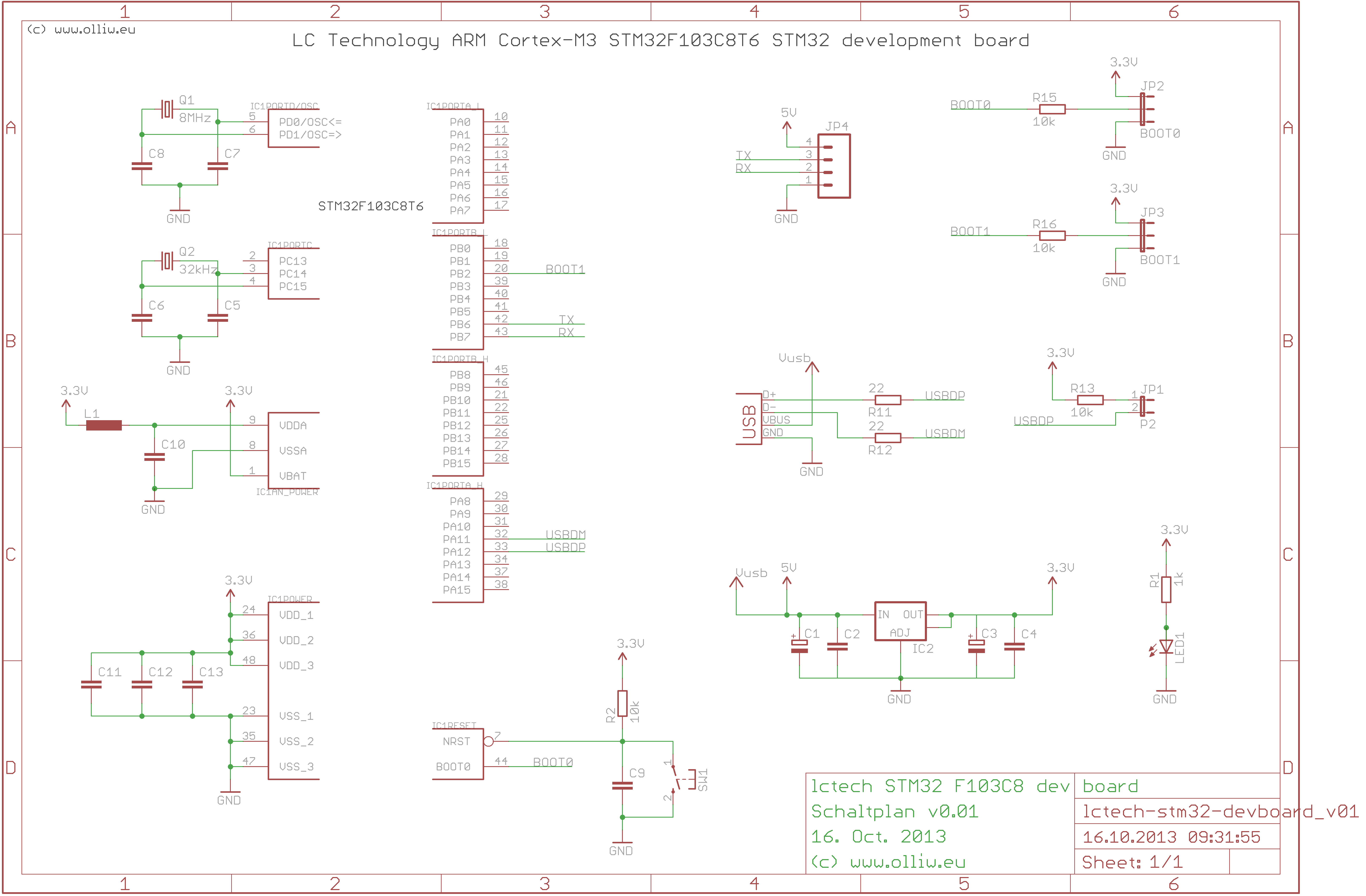
This cost me several hours of frustration, especially since I couldn’t get debugging going. I had no idea if the board was just not executing my code, or if it was some other problem. Fun!
To be continued #
I will likely post more about my experiments with this super-powerful chip, and other, even more powerful in the same family. I’ve a bunch of projects in mind. Should be fun!
I hope this helped you. Feel free to ask me questions. My email address is in the sidebar thingie to the right. Happy hacking!